Special technologies
The Special Technologies team is engaged in:
- Research and development of technologies and constructions necessary e.g. for building electron microscopes working with high or ultrahigh vacuum. The most important of these technologies are electron beam welding, vacuum brazing, the design and manufacture of vacuum feedthroughs, etc.
- Magnetron sputtering of thin metal layers such as Al, Si, Mo, Ti, Ni, Ag, C, ITO, Nb, W, TiN, Si3N4, SiO2, and their combinations. The team also managed the preparation of multi-layer systems for X-ray optics, consisting of nanometer double-layers with total thickness of tenths of a micrometer, with accuracy to tenths of a nanometer.
- Vacuum deposition by means of electron beam heating and spectro-photometric measurements of their spectral reflectivity and transparency.
- Deposition of abrasion-resistant layers like carbon, carbon-nitride, nano-structured multi-layers and carbon-based nano-composites.
- Testing of hard abrasion-resistant layers by a dynamic impact tester (we are one of only two facilities in the Czech Republic that possess this instrument).
Electron beam welding
Electron beam welding is a fusion joining method that applies an electron
beam for local heating. At the point of impact, the kinetic energy of electrons,
ranging from 30 to 200 keV, is transferred into heat which rapidly warms any
material to its melting point. The process takes place in a high vacuum
(pressure 10−2 to 10−3 Pa), most often without
additional material. Thanks to very high power concentration, the focused beam
penetrates rapidly into the metal, producing a deep and narrow weld. As a result
of the clean, high vacuum atmosphere, even highly reactive metals like titanium
or zirconium can be welded. Due to high vapor pressure at the melting
temperature, some metals like Zn, Cd or Mg, cannot be welded in vacuum. Despite
high acquisition costs, electron beam welders are widely used today,
particularly in the nuclear, cosmic, aviation and automobile industries.
The main advantages of electron beam welding include:
- „Knife“ form of the weld with a depth to width ratio of up to 25:1, resulting in minimal deformations and thermally affected zone.
- Welding of refractory metals.
- Very deep welds: with enough power in the beam, up to 300 mm in aluminum, or 100 mm deep welds in stainless steel can be realized.
- High productivity.
- Due to high vacuum working atmosphere, the re-melted zone can be cleaner than the basic material.
Three electron beam welders are installed at ISI Brno, all designed and
manufactured in this institute. All three are equipped with cylindrical vacuum
working chambers and welding manipulators for rotation and linear movement of
the work-piece. The design of all three enables two positions of the electron
gun on the working chamber: either horizontal or vertical. With the gun in the
vertical position, the vacuum working chamber can be extended horizontally.
Tubes (e.g. 5 meters long) can then be welded.
The technical parameters of these welders are:
- The oldest, but upgraded equipment ES-2 has a working chamber 600 mm in diameter and 490 mm in length. It is equipped with a 50 kV/1.5 kW electron gun.
- The “desk-top” EB welder SES-1 has a working chamber 235 mm in diameter and 165 mm in length. It is equipped with a 50 kV/1.5 kW electron gun. Five-meter zirconium tubes have been welded in the vacuum chamber when extended horizontally.
- “Experimental” electron beam welder MEBW-60/2-E with a similar working chamber is equipped with a 60 kV/2 kW electron gun. The electronic equipment of this welder is completely digitalized and computer controlled. This enables, for example, automatic, pre-programmed welding that is perfectly reproducible.
The MEBW-60/2-E welder can also be operated in a mode similar to a scanning
electron microscope. In this mode the objects in the vacuum chamber can be, at a
magnification of up to about 30 times, displayed on the computer monitor, e.g.
to inspect the weld before venting the working chamber. The welder in this mode
can also be used for the precisely localized surface heating needed for
hardening or annealing of thin surface layers.
Applications of electron beam welders at ISI Brno:
- Welding high and ultra-high vacuum components (fittings, valves, etc.).
- Components for nuclear power engineering (e.g. heat exchangers).
- Joining of dissimilar materials (e.g. aluminum to titanium and/or nickel, or silver, copper to stainless steel, titanium to steel, and many other combinations).
- Welding of refractory metals such as molybdenum or tungsten.
- Welding of highly reactive metals such as like titanium or zirconium.
Contact:
Ing. Martin Zobač, PhD.
e-mail: zobac@isibrno.cz
phone: +420 541 514 297
Ing. Ivan Vlček, PhD.
email: iv@isibrno.cz
phone: +420 541 514 297
Detailed information : http://ebt.isibrno.cz/en/EBWelding
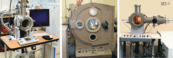
SES-1 desktop e-beam welder (left), improved ES-2 e-beam welder (middle), MEBW-60/2 experimental micro e-beam welder (right)
Vacuum brazing and annealing
The Special Technologies team has great experience with vacuum capillary
brazing. The most commonly used solders are silver- or nickel-based alloys, or
copper. For soldering metals to brittle non-metal materials (e.g. quartz),
so-called “active”, soft solders are applied.
For these technologies, our institute has at its disposal two vacuum
furnaces:
Vacuum furnace PZ 810, manufactured by Tesla Rožnov, with the following
parameters:
- Maximum batch dimensions: diameter 350 mm, height 590 mm.
- Molybdenum heating and shielding elements, allowing long-term heating up to 1400 °C.
- Vacuum 5×10⁻² Pa up to 1 Pa, depending on the charge properties and working temperature.
- Maximum speed of temperature increase: 1500°C per hour.
- Time of cooling in high vacuum: about 8 hours. If needed, the cooling period can be cut short by venting the furnace with inert gas.
Vacuum furnace of our own design and manufacture suitable for vacuum brazing and annealing of small-sized components:
- Maximum batch dimensions: 150 mm in diameter, 200 mm in height.
- The vacuum space can be extended upwards (without heating) for welding objects in the hot zone, if the upper part does not exceed 18 mm (e.g. long tubes to flanges).
- Maximum working temperature: 1100°C.
Contact:
Ing. Martin Zobač, PhD.
e-mail: zobac@isibrno.cz
phone: +420 541 514 297
Ing. Ivan Vlček, PhD.
email: iv@isibrno.cz
phone: +420 541 514 297
Detailed information: http://ebt.isibrno.cz/en/Soldering
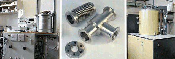
Laboratory vacuum furnace built at ISI (left), examples of vacuum soldering (middle), renovated PZ 810 vacuum furnace (right)
Design and manufacture of feedthroughs
The team of Special technologies realizes research and manufacture of varies types of electric, vacuum-tight and high- or low- temperatures resistant feedthroughs. The technology is based on glass-to-metal seals, either with kovar or other metals (pressure-seals).The feedthroughs are usually welded to flanges or other construction components. To date we have developed the following types:
- One-pin coaxial feedthroughs for working temperatures from –196°C up to +400°C.
- Seven- or twelve-pin feedthroughs for temperatures from –196°C up to +400°C.
- High-current feedthroughs for temperatures from –60 to +300°C.
- High-pressure feedthroughs for the nuclear industry, with working temperatures from –60 up to +300°C.
- Individual, „client“ feedthroughs.
- Special feedthroughs for various instruments such as electron microscopes, ultrahigh vacuum devices, etc.
- Nuclear power engineering.
Contact:
Ing. Martin Zobač, PhD.
e-mail: zobac@isibrno.cz
phone: +420 541 514 297
Ing. Ivan Vlček, PhD.
email: iv@isibrno.cz
phone: +420 541 514 297
Detailed information: http://ebt.isibrno.cz/…feedthroughs
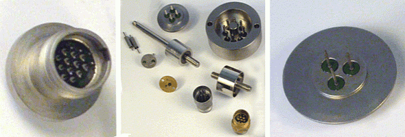
Vacuum feedthroughs examples
Thin layers deposited by magnetron sputtering and their dynamic impact testing
We can deposit thin layers by high-frequency magnetron sputtering in the
commercial equipment LEYBOLD-HERAEUS Z 550, enabling the production of layers
in small series or on single substrates of up to 100 mm in diameter and a
thickness of 20 mm. The machine is equipped with three magnetrons, each with a
Ø152 mm target. This makes it possible to deposit three different materials in
one evacuation cycle. For special applications (for example ion etching) the
substrate can be pre-heated and electrically charged.
Applications of magnetron sputtering:
- We can deposit multi-layers for X-ray optics, in combinations of double-layers such as molybdenum/silicon, nickel/carbon, scandium/silicon and others suitable for X-rays in the wavelength range from 12 to 50 nm. Maximum reflection at perpendicular impact is up to 70%.
- For very short wavelengths (less than 4 nm) multi-layer systems cannot be used because the roughness of the interface causes decreased reflectivity. Nevertheless, the periodical multi-layers are applicable for inclined rays, providing much higher reflexivity than much thicker mono-layer deposits.
- At present we are one of only two places in Czech Republic where characteristic properties of hard abrasion-resistant nano-composite and multi-layer deposits can be evaluated by a dynamic impact tester. During testing the sample surface is impacted periodically by a small wolfram-carbide ball, imitating a dynamic strain of layer/base system of stamping dies, cutting tools, parts of automobile motors, etc.
Contact:
Ing. Jaroslav Sobota, CSc.
e-mail: sobota@isibrno.cz
phone: +420 541 514 256
Detailed information: http://ebt.isibrno.cz/…n-sputtering
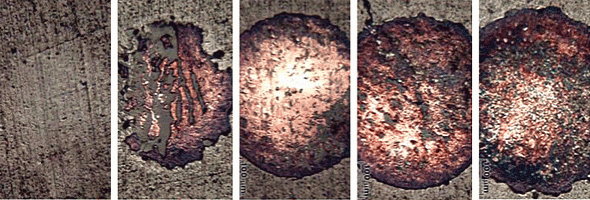
Results of thin layer dynamic impact test
Deposition of interference coatings by electron beam evaporation and spectrophotometric measurement of spectral reflectance and transmittance
Thin layer coatings are prepared by means of electron beam evaporation using a Balzers BAK550 coater equipped with two electron guns. Substrates can be preheated. Our coater is capable of small batch production of circular substrates with the largest diameter of 180mm or rectangles up to 170mm x 120mm. The following materials can be deposited: TiO2, SiO2, Ta2O5, ZrO2, CeO2, HfO2, Y2O3, MgO, Al2O3, MgF2 and Na3AlF6. Application: Interference filters for visible, near UV and near IR part of the spectrum. For example:
- anti-reflection coatings,
- low-loss mirrors,
- cold mirrors,
- heat mirrors,
- dichroic filters,
- bandpass and edge filters,
- beamsplitters,
- polarizers,
- nonpolarizing beamsplitters
- monochromatic filters
Spectral reflectance and transmittance measurements are performed using a
Varian Cary 5E spectrophotometer.
Contact:
RNDr. Pavel Pokorný
e-mail: pok@isibrno.cz
phone: +420 541 514 257
Mgr. Jindřich Oulehla
e-mail: oulehla@isibrno.cz
phone: +420 541 514 226
Detailed information: http://www.isibrno.cz/kgs
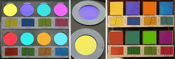
Dichroic filtres – reflection color (left), substrate carrier example (middle), dichroic filtres – transmission color (right)


